
An electrocardiogram (ECG) is a cornerstone of cardiac diagnosis, providing invaluable insights into the heart’s electrical activity. However, the accuracy of ECG interpretation can be significantly compromised by artifact, which represents any extraneous electrical activity that interferes with the underlying cardiac signal. This guide offers a comprehensive overview of common ECG artifacts, their causes, and strategies for mitigation, aiming to enhance the reliability of ECG interpretation and improve patient care.
Types of ECG Artifacts
Artifacts on the electrocardiogram can result from a variety of internal and external causes, from Parkinsonian muscle tremors to dry electrode gel.
Most of the time it will be obvious that you are dealing with artifact on ECG issues and troubleshooting the problem will be straight forward. However, there are occasions when artifact mimics ECG abnormalities that can cause problems for patient care.
In one instance, a cardiac monitoring technician responded to an alarm indicating potential ventricular tachycardia. Upon arriving at the patient’s room, it was discovered that the patient was simply brushing their teeth, causing an artifact that mimicked the dangerous arrhythmia. With a trained eye, you can often learn to spot the underlying rhythm “marching” through this type of artifact. Other times, it’s not that easy.
Here are some types of artifacts you may encounter, along with some tips to help you achieve excellent data quality on your ECG tracings.
Loose Lead Artifact
You will frequently encounter loose lead artifact when dealing with patients who are diaphoretic because the electrodes simply will not stick to the patient’s body. You may also see this type of artifact when placing the electrode over hair.
To troubleshoot this problem, make sure you prep the skin carefully! Consider the tincture of benzoin. It works great for diaphoretic patients. However, tincture of benzoin is flammable! You don’t want to use it for defibrillation pads.
In this example, loose lead artifacts can be seen in leads I and II.
What electrodes do leads I and II have in common?
- Lead I is a dipole with the negative electrode on the right arm and the positive electrode on the left arm.
- Lead II is a dipole with the negative lead on the right arm and the positive electrode on the left leg.
Lead I and lead II share the right arm electrode! That is the electrode that is causing this problem.
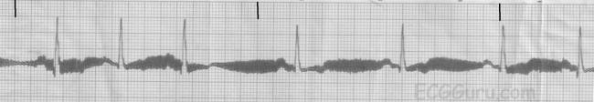
Wandering Baseline Artifact
Wandering baseline artifact presents as a slow, undulating baseline on the electrocardiogram. It can be caused by patient movement, including breathing.
Stopping or accelerating the ambulance can also cause a wandering baseline ECG. Some references suggest that wandering baseline can be caused by loose or dry electrodes. Some paramedics ask patients to hold their breath while they capture a 12-lead ECG. Be aware that this can also alter the patient’s heart rate.
There are times when your patient is acutely short of breath, and it’s simply impossible to capture a 12-lead ECG with excellent data quality.
Muscle Tremor Artifact
Muscle tremor (or tension) artifact is a type of motion artifact. Usually, it’s happening because your patient is cold and shivering. However, it can also happen when patients prop themselves up with their arms.
The example below was obtained from a young, healthy firefighter during routine training. It was cold in the fire station, and he was shivering.
The next example was taken after a large towel was placed over the firefighter. It made quite a difference, didn’t it?
Electromagnetic Interference (EMI)
Electromagnetic interference (EMI) artifact usually results from electrical power lines, electrical equipment, and mobile telephones. In the United States this is sometimes referred to as 60 cycle interference (or 60 Hz pickup).
Creative Commons: ECGGuru.com
To help minimize 60 cycle interference you can set the diagnostic mode of your 12-lead ECG monitor to 0.05 – 40 Hz. As long as the low frequency / high pass filter (the lower number) is set to 0.05 Hz you should get accurate ST-segments.
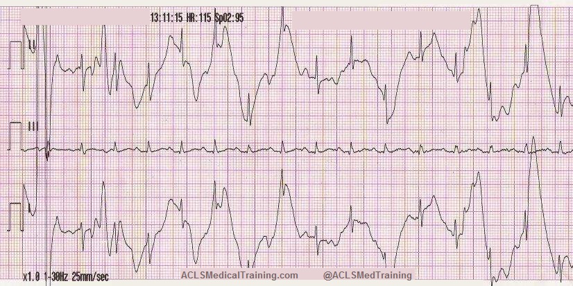
CPR Compression Artifact
This ECG was automatically recorded during a cardiac arrest.
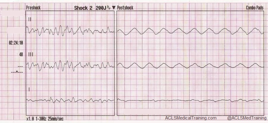
The wavy line after the shock is CPR artifact. Using the small block method (1500/13=115) we can determine that the compression rate was about 115/min. which is perfect! There may be times when CPR artifact makes it difficult to determine the underlying rhythm. However, if you’re performing CPR at a 30:2 compression to ventilation ratio you can see the underlying rhythm during ventilations.
Neuromodulation Artifact
Here’s a type of artifact that is starting to be seen more frequently as implantable neurostimulators become more prevalent.
These devices are used to treat a variety of symptoms, including tremors, seizures, chronic pain, nausea and vomiting related to gastroparesis, problems with bladder or bowel control, visual impairment, and hypertension.
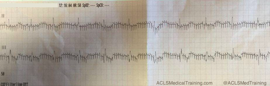
If you see an artifact that looks like this, you should ask your patient if he or she has any implantable medical devices. Some devices can be temporarily turned off with a magnet, but you should consult with the prescribing physician.
Echo Distortion Artifact
This type of artifact is associated with transcutaneous pacing (TCP). Echo distortion causes a pseudo-QRS complex after the pacing spike, which is sometimes referred to as “false capture.”
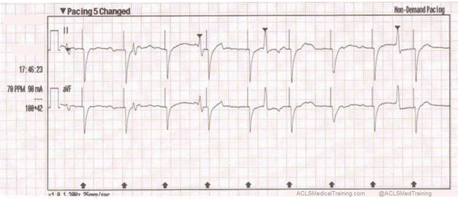
The pacing spike is a graphical representation that an electrical current is about to pass between the pacing pads. It is followed by a short “blanking period” of about 40 ms (one small block) where the monitor essentially “closes its eyes”. If it did not, the signal would go right off the ECG paper!
After the blanking period the monitor “opens its eyes” to see the QRS complex that is created by the pacing stimulus. However, sometimes the monitor catches the pacing current as it returns to baseline causing a pseudo-QRS complex on the ECG. You can read more about the problem of false capture here.
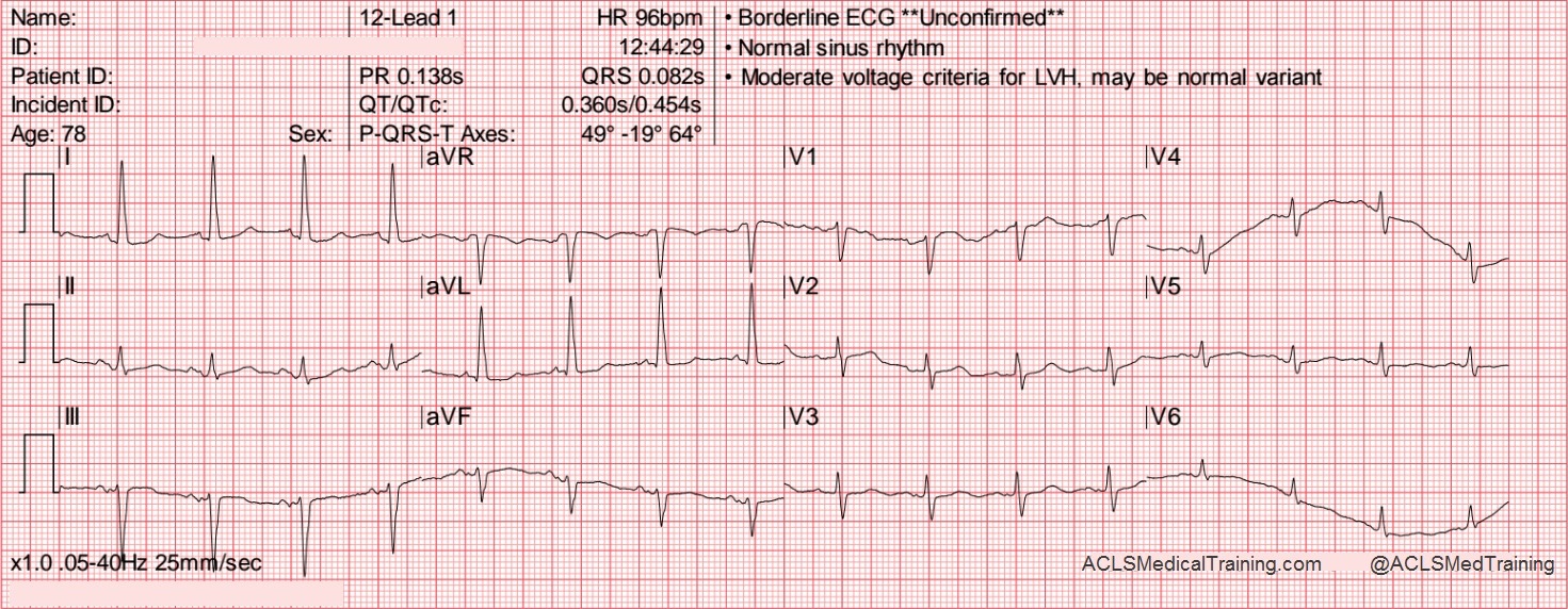
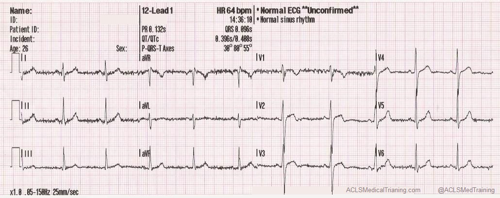
Arterial Pulse Tapping Artifact
This unusual artifact causes large, bizarre T-waves on the ECG. The phenomenon was first reported in 2005 by Özhan et al. as a “bizarre electrocardiogram” thought to be associated with abnormal left ventricular motion.
Subsequent work by Aslanger solved the issue in favor of arterial pulse tapping (which explains why the artifact occurs synchronously with the cardiac cycle on the ECG.)
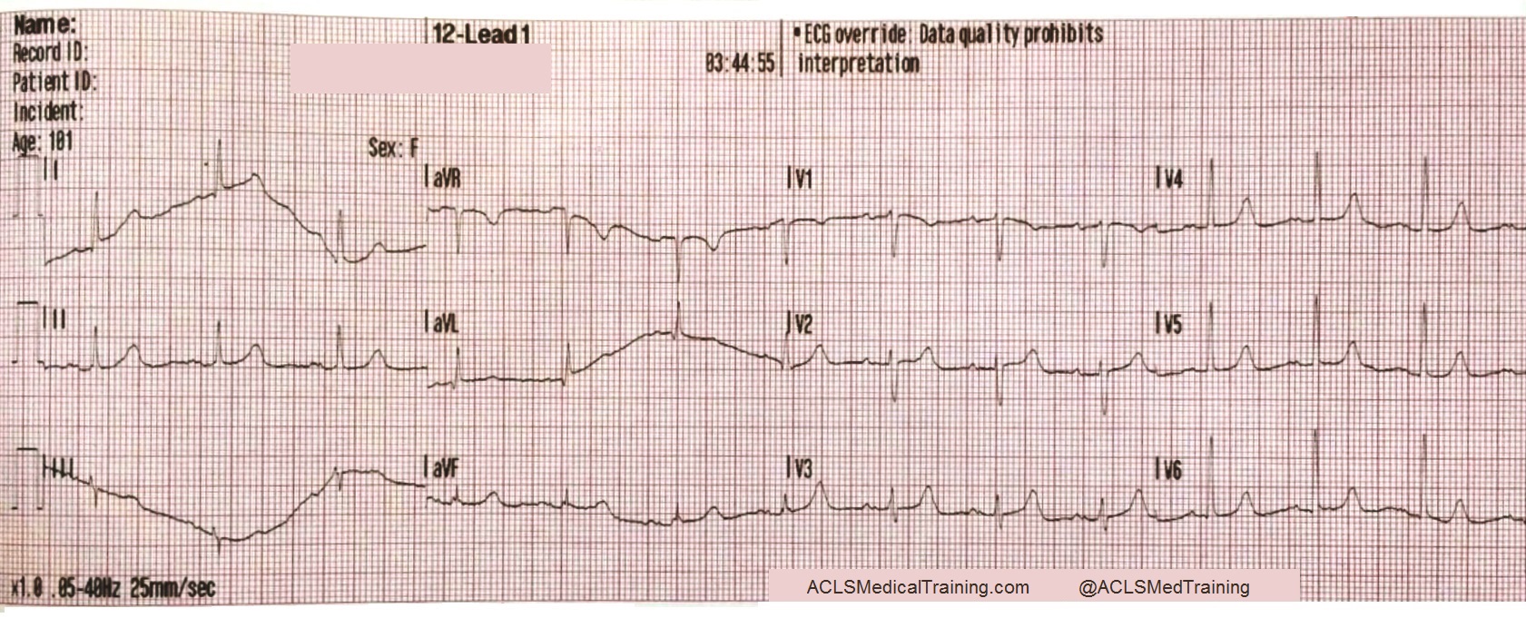
Consider these two ECGs which were recorded from the same patient less than 1 minute apart. The first ECG shows simple motion artifact in leads I, III, and aVL.
Courtesy of Frank Intessimoni (@njmedic3228)
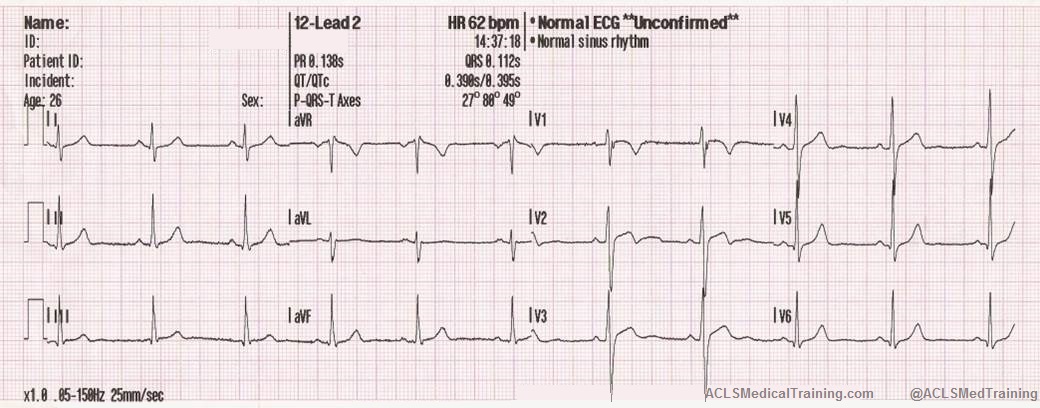
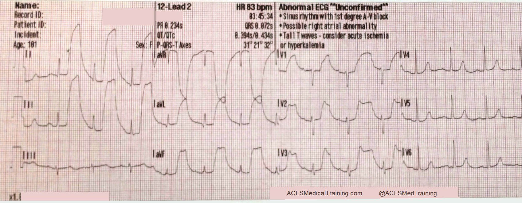
The second ECG shows large, bizarre T-waves that were concerning to the paramedics on the call.
Courtesy of Frank Intessimoni (@njmedic3228)
You will note that the artifact is most pronounced in leads I, II, and aVR. Lead III appears perfectly normal. This suggests that the right arm electrode was placed over the radial artery.
But if that’s true, why is there also an artifact in other leads?
Aslanger explains:
“[O]ne may expect that the leads not connected to the electrode affected by the source of disturbance would be free of distortion, but this is not the case. When one of the limb electrodes is affected by a source of disturbance, it distorts not only the corresponding derivation but also [the others], which are all calculated by mathematical equations…”
“…precordial leads [are also affected] because the Wilson central terminal, which constitutes the negative pole of the unipolar leads, is produced by connecting 3 limb electrodes via a simple, resistive network to give an average potential across the body.”
Get Started With ACLS Certification Training
By understanding common artifacts and their potential impact on diagnosis, healthcare providers can significantly improve their ability to accurately assess cardiac conditions. While recognizing artifacts can be challenging, consistent practice and advanced training are invaluable. To further enhance your ECG interpretation skills and prepare for critical cardiac emergencies, consider enrolling in our online ACLS Certification Training course. Our comprehensive curriculum covers advanced cardiac life support, including in-depth ECG analysis, to teach you everything you need to know to handle high-pressure situations effectively. Take the next step in your professional development and enroll today!
References
Aslanger E, Yalin K. Electromechanical association: a subtle electrocardiogram artifact. Journal of Electrocardiology. 2012;45(1):15-17. doi:10.1016/j.jelectrocard.2010.12.162.
Aslanger E, Bjerregaard P. Mystery of “bizarre electrocardiogram” solved. Journal of Electrocardiology. 2011;44(6):810-811. doi:10.1016/j.jelectrocard.2011.04.001.